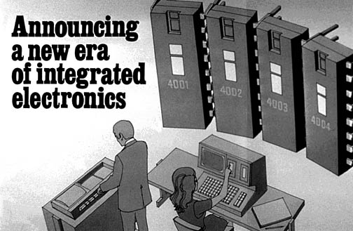
Intel's November 15, 1971 product announcement in Electronic News
Complete Artwork, Schematics, and Simulator for Intel MCS-4 (4004 family) microprocessor chip-set: "Together again after 38 years!"
| 4001 ROM —Newly re-created | 4002 RAM | 4003 I/O Expander | 4004 CPU |
|---|---|---|---|
 |
 |
 |
 |
| Component type | Layout | Schematics | Difference |
|---|---|---|---|
| Transistor: | 1807 | 1741 | 66 |
| Resistor: | 427 | 427 | 0 |
| Capacitor: | 66 | 0 | 66 | ESD protection: | 8 | 8 | 0 |
| Total: | 2308 | 2176 | 132 |
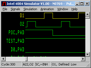
After finishing the netlist comparison, I was motivated to simulate the extracted circuit to ensure correctness, and to see whether the whole circuit would behave same upon executing assembly code as described in the MCS-4 User Manual (PDF 29.4Mb). So I wrote a switch-level simulator. For easier testing, I gradually added more and more feature, and I replaced rough temporary solutions with more mature ones. I realized that a number of problems came from shortcomings of the simulator logic, and so I improved it until it became reliable.
Simulating the entire chip-set required re-creating the missing schematics and masks
After completing the verification work for the 4004 microprocessor, I yearned to simulate a complete microcomputer set (CPU, ROMs and RAMs) at the transistor level. In late December of 2008, Tim McNerney sent me scans of the Intel 4002 RAM mask proofs. This was directly usable for the simulator, but the schematics were not available in any form. Fortunately, I found that by reusing blocks from the CPU schematics, I could reproduce a correct schematic diagram in a relatively short time. The situation with the ROM was not as straightforward. To get me started, Tim sent me two high resolution photomicrographs of the Intel 4001 ROM, one of the unmodified chip, and one of the chip with the metal-layer etched away, revealing the transistors. Unfortunately the quality was not suitable for automatic mask extraction. The only expedient alternative was to redraw the required mask layers by tracing the photographs, and to reverse engineer the schematic. For the sake of project completeness, this is what I did.
At first only the individual chips were simulated separately by generating the necessary test patterns for the external pins of RAM/ROM (which required a clock-cycle level accurate simulator of Intel 4004 CPU too). Then I connected the individual simulators together through a TCP/IP server application. This way the CPU/RAM/ROM simulators can be run in parallel, just as they were wired in a real system. Sharing the resources of several computers was considered for providing more screens to the schematic/layout and simulator windows; but it was not necessary to get more processing power and more memory for the entire simulated environment.
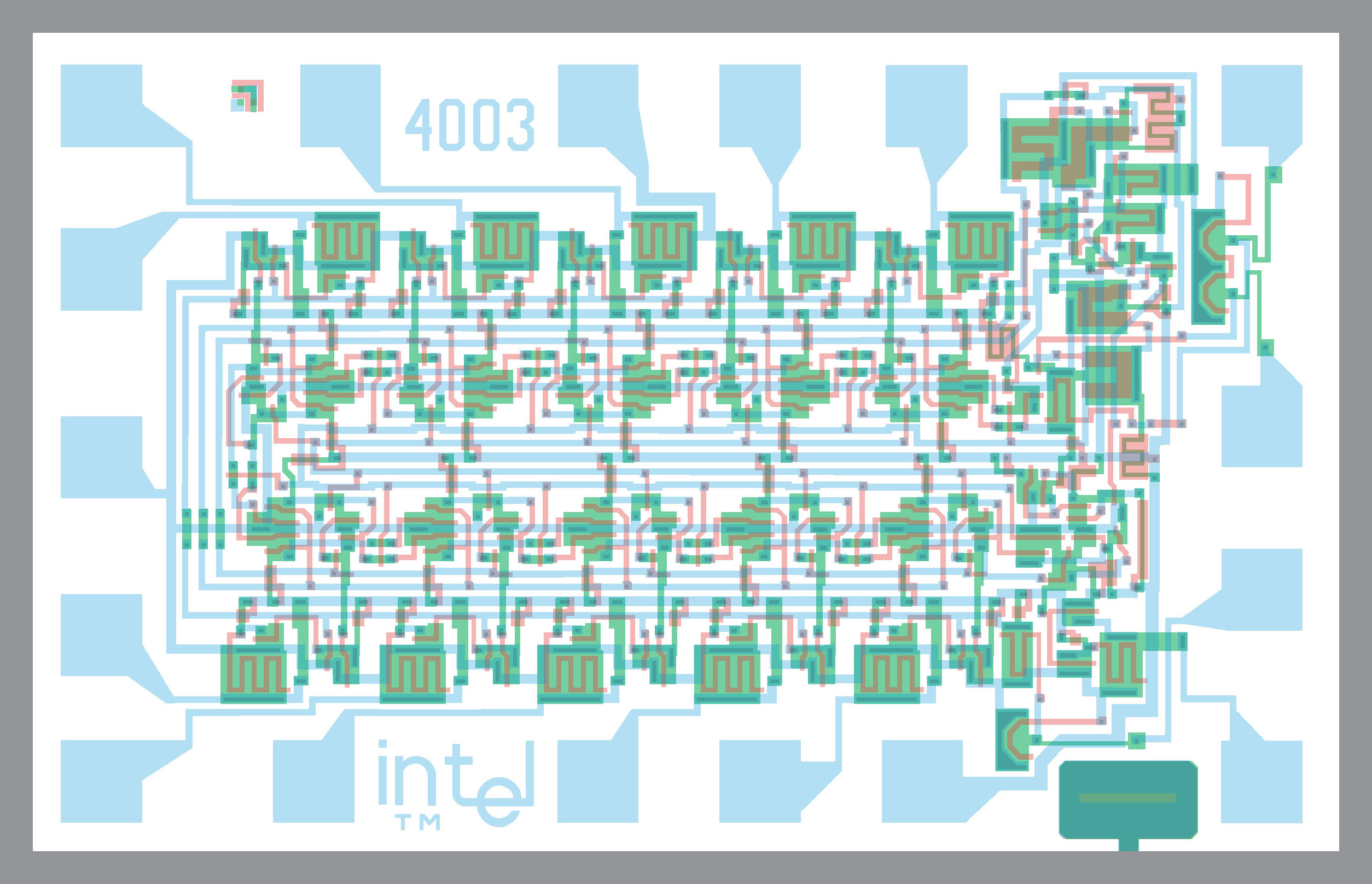
In October 2009, Tim sent me the mask artwork for the 4003, a 10 bit shift register used as an I/O expander. Much like I did for the 4002 RAM, I generated the schematic, and the result was added to complete the MCS-4 simulator package.
In November 2009, Intel gave us permission to publish our work under a non-commercial Creative-Common license.
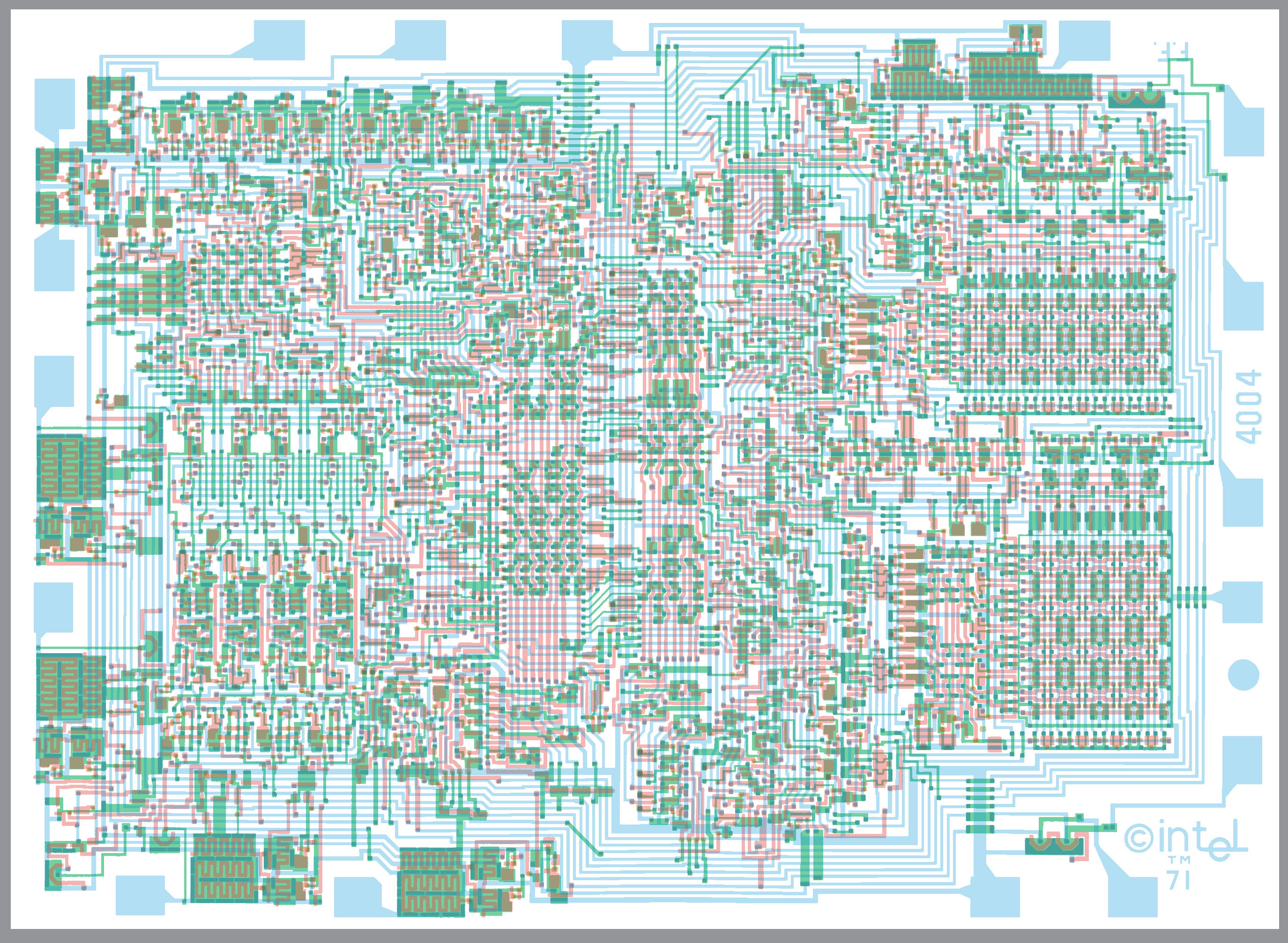
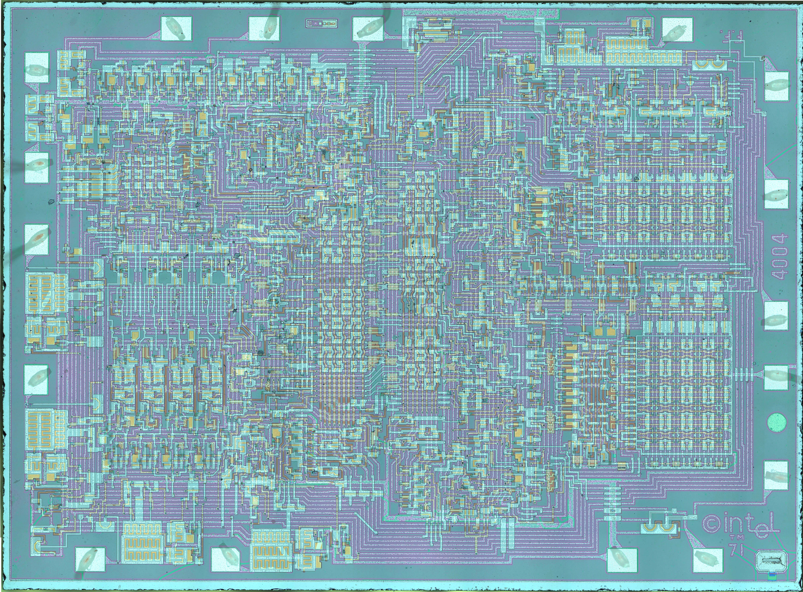
MCS-4 Composite Mask Artwork
The 4001 Mask-Programmable ROM
The 4002 RAM (External Registers)
The 4003 10-bit Shift Register (I/O Expander)
The 4004 CPU
MCS-4 Schematics
Scans of the original 4004 schematics (three drawings) are available from the Intel Corporate Archives, along with scans of the manual mentioned above and the 4004 mask proofs. These were transparencies bound together for reference purposes, not the original lithographic masks. Due to distortion and aging, we had to "clean them up" and re-verify them.
Composite Photomicrographs
Here are links to two synthetic photomicrographs, one of the 4001 and one of the 4004. Tim McNerney created them using Photoshop by layering a transparent photo of the original chip with a photo of the chip that has had its metal layer etched away using hydrofluoric acid (a really dangerous chemical--don't try this at home!). By combining the etched and unetched photos in this way, you can see the metal wires and the transistors together in the same image. It is almost like looking at an X-ray of the chip.
The MCS-4 Simulator and Chip-Set Data
Here you can download a zip file with the individual mask, schematics, documentation, and Microsoft Windows executable.
Quick start
- First extract it using your favorite file archiving program (mine is the free, no strings attached 7-zip)
- Inside the folder i400x_analyzer20091114 is an application called i400x_analyzer.exe, double-click it to run the program.
- The first time you run it, keep the defaults checked, and click on "OK"
- Four windows will appear, then a little dialog box. Click "OK" to make the dialog box go away.
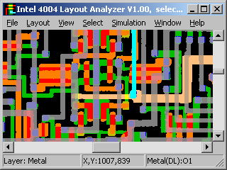
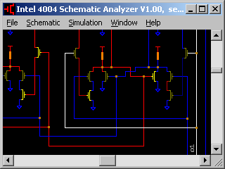
- For casual exploration, the most interesting windows are the Layout Analyzer and the Schematic Analyzer. Move the Layout window to the right to expose the Schematic window.
- Click on the RM output pad. You will notice that the same pad and wire highlighted in the Schematic window.
- Select the Schematics window. Then click on the wire directly above the one that is highlighted in white. This will highlight the R0 output pad in the Layout window.
- Back in the Windows file explorer, double-click on readme.txt for more documentation. For quick access, here is a link to the same readme.txt file.
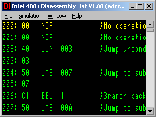
A Few Screen Shots
As you can see in this screen shot of the Layout window, the simulator uses a different-looking color scheme than Tim chose for the mask composites. In the simulator, the colors also indicate logic levels, and metal looks gray. In the mask composites, Green = Diffusion, Red = Polysilicon, and Blue = Metal. These colors were inspired by the book Introduction to VLSI Systems by Mead and Conway, as well as full-custom VLSI CAD systems that Tim used professionally, including Mentor Graphics and UCB Magic.
Legal Notices
- The software (e.g. simulators) and engineering documents (e.g. schematics) are provided "AS IS" with no warranty expressed or implied. Fitness for any particular purpose is not guaranteed. The authors do not accept any liability for use of this information.
- The works on this web site are licensed under a Creative Commons Attribution-Noncommercial-Share Alike 3.0 License.